Smart Contract Design: Recommendations and Security
The design of a smart contract lays the foundation for its overall security, extensibility, and maintainability. It shapes the components it contains and the relationships between them. Investing time in a secure, robust design is crucial as it not only helps prevent a range of security issues but also contributes to the system's long-term sustainability. Conversely, an insecure or poorly planned system design can lead to vulnerabilities that can be incredibly hard to mitigate, making the system difficult to manage and maintain and potentially resulting in significant financial losses.
In this section, we will look at a few options around designing secure smart contract systems and visualizing them for future documentation and maintainability.
Composable Design
Composability is a fundamental aspect of software development and is particularly applicable in the context of smart contracts. Composability involves arranging and integrating distinct software components to form new systems or outputs. It provides a modular structure that can prove beneficial, especially for developers starting from scratch or those seeking to refactor an existing code base. Such a structure results in a system that's easier to understand and maintain. It enhances resilience by containing errors or vulnerabilities within individual modules, drastically reducing the associated risks of a large-scale system compromise.
When composability is implemented correctly, each smart contract can be a foundational building block for other projects. A smart contract can exist in its source unit, i.e., a deployed smart contract. It can also comprise one or more abstract contracts separating business logic but eventually merged by the compiler into a single source unit. This means developers don't necessarily need to start from scratch or reinvent the wheel but can instead leverage these existing contracts to save time and resources. Furthermore, when building atop well-known libraries like OpenZeppelin, some degree of modularity is already present, providing a good starting point.
Three central principles underpin this composability: modularity, autonomy, and discoverability. Modularity refers to the capacity of individual components to perform specific tasks. The separation into modules should be based on the separation of concerns in the business logic domain. Autonomy means that these composable components, each Ethereum smart contract, can operate independently. A smart contract can be an isolated system without external factors unless specifically designed to integrate with an external system. This feature fosters faster development for localized features and enhances testability.
Discoverability is also critical, as it ensures the public availability of source code for components. For already deployed publicly available components, users and developers can compile publicly available source code and match the bytecode hash against what is deployed on-chain to verify the integrity. Blockchain explorers like Etherscan even offer this as a service. In addition, this facilitates developers to fork specific functionality and entire systems for use cases that can't be easily covered by modularity alone.
Composability can provide various benefits as an umbrella for modularity, autonomy, and discoverability. It can significantly speed up future development while keeping the code understandable to third-party readers like users and security auditors. As a neat side effect, it fosters community trust and might inspire other developers to innovate based on your code. To implement composable patterns, here are some tips for developers who already have an existing code base to work with and those starting from scratch.
For Developers Maintaining An Existing Code Base
Suppose you're working with an existing codebase, particularly one initially created for a proof-of-concept or an MVP. In that case, it may not be appropriately modularized. Transitioning from a monolithic system to a modular architecture can seem daunting. Still, an incremental approach can alleviate much of this complexity.
Begin by identifying different functionalities within the system and mapping out the existing logic and data flows. Once you've identified these functionalities, you can detach them from the main body of the code, one at a time. Implement thorough testing for each newly isolated module, ensuring its functionality remains consistent before and after extraction. This step will also allow you to spot and address any potential points of failure early in the process, mitigating the risk of more impactful issues occurring down the line. Patience and careful planning are key here, as rushing the transition can inadvertently introduce new errors or vulnerabilities.
For Developers Starting From Scratch
If you're starting from scratch, you can build a composable architecture from the get-go. The key is to clearly define the functionalities your system requires and consider how these can be broken down into distinct, independent modules.
When defining your modules, aim to encapsulate specific functionalities while minimizing dependencies. Each module should only have the permissions necessary to perform its role and nothing more, following the Principle of Least Privilege. This approach can create a robust and flexible system, reducing the potential for errors and making future modifications easier.
Starting with a blank canvas provides an excellent opportunity to build a modular architecture. The key here is planning - take the time to clearly define the functionalities your system requires and consider how these can be broken down into distinct, independent modules. Draw a map of the proposed system, visualizing how these modules interact and communicate. This planning stage can help identify potential problems or vulnerabilities before a single line of code is written, saving significant time and resources.
When defining your modules, strive to encapsulate specific functionalities while minimizing dependencies. This approach can help create a robust and flexible system, reducing the potential for errors and making future modifications easier. Remember that each module should only have the permissions necessary to perform its role and nothing more, per the Principle of Least Privilege. This security measure can limit the potential damage an attacker can inflict if they gain control of a single module.
In all, for established and new projects, the essence of modular smart contract design lies in careful planning and execution. A well-architected system with a clear separation of concerns and trust zones and adherence to the Principle of Least Privilege is a formidable defense against many common vulnerabilities, providing a foundation for secure and successful smart contract projects.
Architecture Diagrams
System Architecture Diagrams (SAD) illustrate the smart contracts within your system, their interconnections, and their interactions with external systems or actors. Using various shapes or colors, you can distinguish different contract types, such as upgradeable, proxy, or library contracts. Arrows are used to signify information or control flow.
For creating these diagrams, tools like draw.io, Lucidchart, or Microsoft Visio can be used to create these diagrams. Additionally, for smart contracts, tools like Surya can generate a graphical overview of your contract's inheritance tree, which can then be incorporated into your architecture diagram.
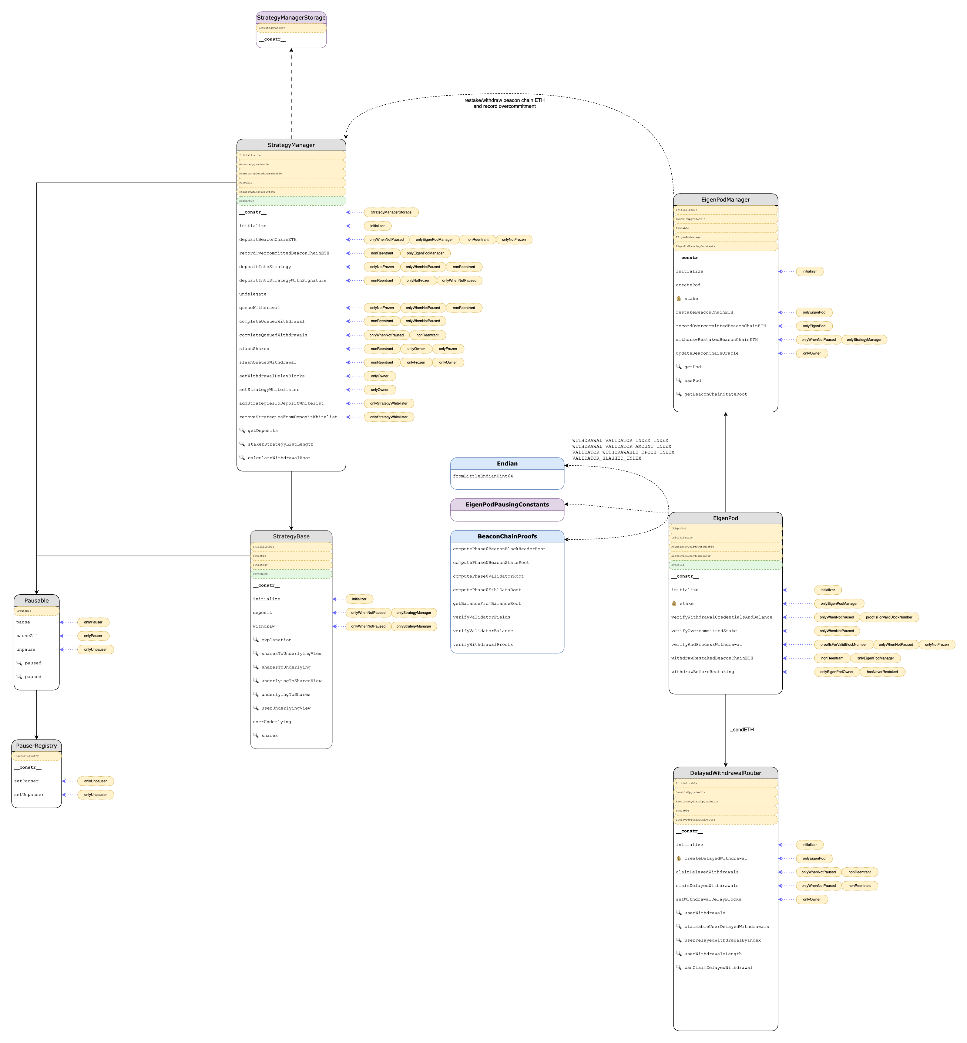
Architecture diagrams serve multiple purposes. Firstly, they are used to simplify complex systems. They convert detailed information into an easily understandable format. Viewers can observe how things interact and understand the cascading effects. Secondly, they can enhance collaboration and communication. In software engineering, consistency is a significant concern. Miscommunications or discrepancies might occur among developers and project teams. Maintaining accuracy, standardization, and detail in diagrams helps improve collaboration. An excellent example of a (partial) system architecture diagram has been built by me in the course of an audit for EigenLayer:
Whatever the definite purpose of the architectural diagram, it can be challenging to efficiently build as it requires a careful balance between automatically generated and manually created ones to minimize workload, address different concerns, and cover multiple abstraction levels of the system. As your design evolves, keeping diagrams updated demands additional effort. Modern architectures introduce extra complexities, which reflect in the charts and might lead to the emergence of additional concerns. Some guidelines you should consider when building your system architecture diagrams are:
- The number of diagrams chosen for representation significantly affects the comprehensibility of the system's architecture. This decision should be based on various factors, including the nature and complexity of the architecture, the skills and experience of the software architect, available time, the amount of work required for maintenance, and what aids in addressing stakeholders' concerns. It's a balancing act: having too few diagrams could leave portions of the architecture undocumented. At the same time, too many could unnecessarily increase the effort required to maintain consistency.
- Consistency, both structural and semantic, across diagrams is critical for accurately interpreting the system's architecture. Structural consistency refers to maintaining uniformity in the diagrams' aesthetics - boxes, shapes, borders, lines, colors, etc. On the other hand, semantic consistency means that all diagrams should be periodically synchronized to align with the latest code changes and interconnected. Maintaining this consistency ensures that changes in one diagram are reflected across others, reducing misunderstandings and inaccuracies.
- Fragmentation occurs when two or more diagrams illustrate the same quality attribute but individually remain incomplete. Having multiple diagrams may challenge understanding the architecture and its maintenance. To avoid this, developers should remove diagrams that do not reflect relevant quality attributes linked to architecturally significant requirements or consolidate them. This practice enhances the diagrams' comprehensibility and relevance.
- Traceability in diagrams is vital for version control and historical referencing. Developers should use tools that allow them to check the history, compare different diagram versions, and swiftly revert to a previous version. This enables tracking of architectural changes over time and eases the process of returning to an earlier version in case of a mishap or design alteration.
- Legends are essential in diagrams, primarily when a standard architectural description language like UML isn't employed. Legends should detail every diagram piece, including boxes, shapes, borders, lines, colors, acronyms, etc. This helps all viewers understand the diagram correctly, irrespective of their familiarity with the specific system or the architecture in general. If a standard architectural description language is used, mentioning this in the legend will suffice, as viewers can refer to the language's specifics to comprehend the diagram.
Keeping system architecture diagrams for smart contract development updated is a key concern; three primary approaches are often considered to address this.
The first is automatically generating diagrams from source code. This straightforward approach helps maintain consistency between the diagrams and the code. But due to the limitations of existing tools, it may not be feasible to generate completely accurate and meaningful diagrams solely based on the source code. This means some level of manual intervention might still be required. Len Bass has suggested that in an ideal development environment, "the documentation is available for essentially free with the push of a button," an aspiration pointing towards auto-generated diagrams. Regrettably, as of now, we have yet to fully attain this level of automation.
The second strategy is to generate source code from diagrams. Under this method, diagrams are first designed using a dedicated tool. These diagrams then serve as the basis for generating source code skeletons (for instance, components/packages with boundaries and APIs), which developers subsequently elaborate on with more specific code. The critical aspect of this approach is that any change in the architectural setup must be initiated from the diagram itself. This change can automatically regenerate or update the relevant code skeleton. It's an approach that ensures that the diagrams and the code remain consistently aligned. However, it does necessitate a high level of discipline in managing changes.
Lastly, there is the option of manual updates. In this case, diagrams are updated manually each time a new feature that impacts the architectural design is implemented. To ensure that all code changes are accurately reflected in the diagrams, it's recommended to make the updating of diagrams part of the 'definition of done' in the development process. This approach, however, comes with a significant caveat. It can easily lead to outdated or inconsistent diagrams, primarily if developers neglect or choose not to update them. Therefore, while it's an available option, it's typically less desirable than the other methods.
Given the existing tools and their limitations, the recommended approach is to blend automatic generation and manual creation of diagrams. For instance, you can auto-generate diagrams that tools can reasonably render from source code without excessive clutter or meaningless information. Diagrams prone to frequent development changes or static diagrams, such as context, reference architecture, package, class, and entity diagrams, can fall into this category.
However, in cases where it's not immediately clear from the source code how the system satisfies specific quality attributes (e.g., availability, scalability, performance), the automatic creation of diagrams may be insufficient. Therefore, it needs to be complemented by manually modeled diagrams. Examples of such diagrams include sequence diagrams, state diagrams, concurrency diagrams, deployment diagrams, operational diagrams, etc.
Sequence Diagrams
System Sequence Diagrams (SSDs) are a potent tool in software engineering. These diagrams showcase process interactions chronologically, detailing the procedures, objects, and communication sequences necessary to fulfill a particular functionality. SSDs are often aligned with use case realizations in the 4+1 architectural view model, occasionally referred to as event diagrams or scenarios.
The essence of SSDs is in mapping out external events generated by actors, their sequence, and potential inter-system events within a use case context. It emphasizes that all systems should be considered black boxes, focusing squarely on events transitioning across the boundary from actors to systems. The article underscores the importance of SSDs for the primary success scenario of a use case and for regularly occurring or intricate alternative procedures.
An SSD visualizes parallel processes or objects (lifelines) that exist concurrently and the messages exchanged between them (represented as horizontal arrows) in the order they happen. This offers a graphical approach to defining simple runtime scenarios.
A comprehensive SSD should encapsulate the following:
- External actors
- Methods invoked by these actors
- Return values tied to the preceding methods
- Indication of loops or iteration areas
Professionals commonly use SSDs in project development to exhibit how specific tasks are executed between users and the system. These tasks could range from repetitive and simple to complex. The goal is to represent the use case in a visual layout. Understanding a sequence diagram requires familiarity with the Unified Modeling Language (UML). Reading an SSD starts at the top with the actor(s) or system(s), and the actions performed are represented by lines extending between the lifelines. Messages appear at the top or bottom of an SSD to illustrate the action in detail. Each subsequent action or response is located under the previous one, providing a detailed depiction of the order of actions.
sequenceDiagram
    autonumber
    actor Alice
    Alice->>Bank: deposit funds
    loop
    Bank->>Bank: assign funds
    Bank->>Bookkeeper: update ledger
    Bookkeeper->>Bank: confirm
    end
    Note right of Bank: Open positions also absorb a partial amount of the deposit
    Bank-->>Alice: mint and transfer representation tokens
In an SSD, if a lifeline corresponds to an object, it signifies a role. Leaving the instance name blank can indicate anonymous and unnamed instances. Messages, represented as horizontal arrows with the message name written above, show interactions. Solid arrow heads represent synchronous calls, while open arrow heads represent asynchronous messages. Dashed lines depict reply messages. If a caller sends a synchronous message, it waits until the message is done. In contrast, if a caller sends an asynchronous message, it can continue processing without waiting for a response.
Sequence diagrams can offer a transparent manner to display how different parts of your system interact over time. They're valuable for illustrating how your smart contracts interact with each other and external systems, potentially revealing vulnerabilities or design flaws. Tools such as WebSequenceDiagrams or Draw.io can create these diagrams, offering user-friendly interfaces and numerous customization options to suit your needs.
Data Separation Patterns
In designing smart contract systems, finding the right balance between maintaining the simplicity of design and ensuring high levels of security and efficiency is crucial. Data separation might seem initially attractive to protect data integrity and allow for easy system upgrades. A clear example of this is the Diamond pattern (ERC-2535). This design pattern promotes contract upgradability by delegating function calls to facets, keeping logic and data separate. Yet, as tempting as it may appear, especially when a system is anticipated to evolve over time, the trade-offs can be substantial.
While this might seem initially appealing, it's important to reassess this perspective with a more nuanced understanding. Instead of strict separation into data contracts and logic contracts, data should ideally remain integrated wherever possible. The true art of smart contract architecture lies not in separating storage but in creating concise and well-defined data structures. These structures should be carefully designed to avoid straying across component boundaries, removing the need for pervasive separation.
The Eternal Storage pattern provides a counterpoint to this perspective, offering a solution for persistent data storage that remains consistent even when a contract's logic changes. It separates data into its own contract, preserving data even as the business logic evolves. With data points being stored and retrieved by generic getters and setters based on an ABI-encoded key, there is high gas cost and the potential of key collisions (especially regarding dynamic data types) associated with the pattern. This state separation can introduce challenges and complexities that must be carefully weighed against its benefits.
An elegant, smart contract system architecture should strive to strike the right balance of domain separation. This approach facilitates the creation of a design that's not only modular but also maintains a localized state with ease. It allows for the seamless execution of complex business logic, thus maximizing the system's overall efficiency. Experience suggests that patterns which completely detach data storage from business logic are challenging to comprehend, audit, and test. These complexities, common in patterns like the Diamond and Eternal Storage patterns, undermine the assumed benefits and often outweigh the advantages of such separation.
The pitfalls associated with data decoupling can also contribute to heightened security risks. When business logic is tightly coupled with its associated data, it becomes inherently easier to understand, test, and secure, resulting in fewer security vulnerabilities.
While promising on the surface, state separation patterns often compound complexity during development, impeding efficient debugging due to the scattered nature of data and logic. Moreover, inspecting such smart contracts on-chain can be challenging, as the broad distribution of contracts complicates obtaining a cohesive system view. This is particularly problematic during incident response procedures following security breaches, where rapid understanding of the system's state is vital. The increased opacity introduced by state separation can hinder quick remediation, potentially exacerbating the fallout. Therefore, it's crucial to consider these implications when deciding on your smart contract system's architecture.
Therefore, as a developer seeking to create a secure system architecture, it's essential to withstand the reflexive urge to implement fancy state-separating patterns and instead focus on designing well-encapsulated, localized state management with clear domain boundaries. This approach, when combined with thorough testing and auditing, can lead to a smart contract architecture that is more readable, testable, and secure.
The ultimate goal of smart contract development should be to create a system that functions correctly and can be easily understood, maintained, and upgraded in the future. Simplicity and clarity should be as high a priority as security and efficiency in your design considerations. As developers navigate this landscape, the temptation to use patterns like the Diamond or Eternal Storage pattern should be balanced with the potential complications and security risks they might introduce.
Diamond Pattern
While storage-separating design patterns, such as the diamond pattern, may seem appealing due to their modular design and potential upgradeability, they often present a complex terrain that can breed potential security vulnerabilities. Therefore, it is generally advised to approach such patterns cautiously or even avoid them if possible. Nonetheless, for those instances where the diamond pattern is deemed indispensable, it is vital to follow specific security guidelines to safeguard contract execution and data integrity.
In proxies and upgradeable solutions, renowned providers like OpenZeppelin have delivered reliable and comprehensively documented tools for UUPS/Transparent/Beacon upgradeable proxies. However, they have consciously omitted the inclusion of EIP-2535 from their library offering. Developers who need to use third-party libraries should do so with heightened diligence.
When building the smart contract system's business logic, a critical consideration is the fragmentation of the logic into distinct facets. This strategy increases modularity, making the codebase easier to audit, test, and maintain. Consequently, developers can focus on enhancing and maintaining particular contract facets without being overwhelmed by a monolithic codebase. Changes to a specific facet should not affect the business logic contained in other facets.
The diamond pattern relies on proxy contracts. Its initialization during deployment should include a valid DiamondCut facet contract address. This function, diamondCut(), provides logic for adding, removing, or replacing facets and functions. Without DiamondCut and the diamondCut() function, the Diamond proxy will become inoperable.
When new state variables are introduced into a storage struct, their position is critical. They should always be appended at the end of the struct to prevent overwrites and referencing errors. Similarly, if utilizing the AppStorage pattern, state variables should not be declared or used outside the single shared struct across all facets. If a design requires multiple structs, explicit calls to diamondStorage() are still recommended.
Nested structs should be avoided unless there are no plans to add more state variables to the inner structs. Directly nesting structs can restrict the ability to introduce new state variables during upgrades without overwriting storage slots of variables declared after the struct. As an alternative, new state variables can be introduced into structs stored in mappings, as the storage slots' calculation for variables in mappings is different and discontinuous.
Moreover, it's crucial not to add new state variables to the structs used in arrays. Any alterations to the struct's size and layout can inadvertently affect the size of the array, possibly leading to indexing issues or other anomalies.
Like other proxy patterns, each variable in the Diamond pattern should have a unique storage slot to prevent overwriting when two different structs occupy the exact location. Another critical security measure is the protection of the initialize() function. This function, often used to assign privileged roles, can present a security risk if left unprotected at deployment. To prevent bad actors from exploiting this vulnerability, developers should ensure proper access control or call the function during deployment and prevent further calls.
Lastly, caution is advised against any facet that can call the selfdestruct function. If triggered, it could result in the removal of the entire contract and the potential loss of funds or data. This risk is especially prevalent in the Diamond pattern, where multiple facets can access the proxy contract's storage and data.